Basic Electrical Training Card
SBC MicroTrainer — Version 1 is a pocket-sized training tool that doubles as a functional circuit board. It lets students experiment with series and parallel circuits using built-in LEDs and switches, providing a hands-on way to understand voltage, current, and resistance. Designed for classroom demonstrations, it’s a compact, engaging way to teach foundational electrical concepts.
SBC MicroTrainer — Version 1
A Pocket-Sized Training Tool
I designed this SBC MicroTrainer — Version 1 Business Card as a hands-on teaching tool that goes far beyond a traditional business card. Instead of just printed contact information, it’s a fully functional electronic circuit board designed to help students explore the foundational concepts of series and parallel circuits.
This card combines electronics education and design creativity—a compact, visual way to demonstrate how current and voltage behave in different circuit configurations.
Getting Started with the SBC MicroTrainer
The SBC MicroTrainer is a small training board designed to help you see how electricity behaves in real circuits.
You’ll use it to learn the difference between series and parallel circuits, practice using a multimeter, and explore voltage, current, and resistance.
🔌 Powering the Board
This switch on the top left of the board is called the master switch — it controls power to the entire board.
To turn the board on, slide the switch to the right.
When the switch is off, no current flows through the board.
Once the board is powered, you can:
Explore the components that make up a simple circuit — power, ground, switch, resistor, and LED
Observe how LEDs behave in both series and parallel circuits
Measure voltage and current at different points
See how resistance affects circuit behavior
Practice using your multimeter correctly on a real circuit
The SBC MicroTrainer gives you a safe way to explore and measure what’s really happening in an electrical circuit — the same principles you’ll find in a vehicle’s wiring system.
Exploring the Components of a Simple Circuit
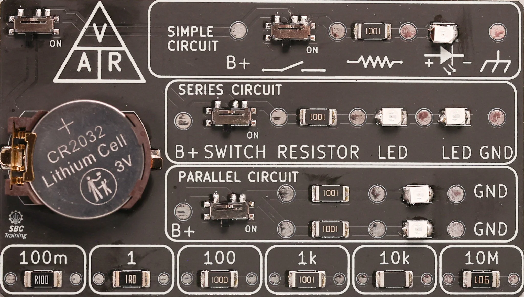
At the top of the SBC MicroTrainer, you’ll find a simple series circuit that demonstrates how electricity flows through basic components.
Each part of this circuit plays an important role — just like in an automotive electrical system.
Simple Circuit
Here’s the path the current takes:
B+ Test Point – This is the positive power source. It represents the battery’s positive terminal.
Switch – The sliding switch controls whether current can flow. When it’s turned on (to the right), the circuit is complete, and power can move through the rest of the components.
Resistor – The resistor limits the amount of current flowing through the circuit. This protects the LED from too much current and demonstrates how resistance affects voltage drop.
LED (Light Emitting Diode) – The LED lights up when current flows through it in the correct direction. This shows that LEDs only conduct one way and helps visualize current flow.
Ground (GND) – The ground point completes the circuit, returning current to the negative side of the power source — just like the chassis ground in a vehicle.
You’ll notice test points placed between each component.
These are used to take voltage measurements with a multimeter so you can see how voltage changes as it moves through the circuit.
Measuring Voltage Across the Entire Circuit
Now that you understand each component, let’s make your first voltage measurement using a multimeter.
Turn on the master switch by sliding it to the right.
Set your multimeter to DC Volts (V⎓).
Place the red meter lead on the B+ test point — this is your power source.
Place the black meter lead on the Ground (GND) test point — this is your return path.
You should see a voltage reading close to the battery or supply voltage.
If you’re using a coin cell, this will be around 3 volts.
Measure the voltage of the simple circuit
This measurement shows the total voltage available across the circuit when power is turned on.
In the next steps, you’ll measure voltage drop across individual components to see how that voltage is divided in a series circuit.
Measuring Voltage Drop at the Switch
Next, let’s measure the voltage drop across the switch.
What is Voltage Drop?
Voltage drop is the difference in electrical potential between two points in a circuit.
It tells you how much voltage is used or lost as current flows through a component.
When a circuit is working properly, voltage drop helps you see where energy is being consumed or blocked.
Measuring at the Switch
Keep your meter set to DC Volts (V⎓).
Place the red meter lead on the test point before the switch (B+ side).
Place the black meter lead on the test point after the switch (output side).
When the switch is OFF, you should see full battery voltage (for example, around 3V or 5V).
When the switch is ON, you should see close to 0V, since the switch is now allowing current to pass freely.
This shows that a closed switch has almost no voltage drop, while an open switch blocks voltage — a key idea in both automotive and general electrical diagnostics.
Measuring Voltage Drop Across the Resistor
Now let’s measure the voltage drop across the resistor in the circuit.
This shows how much of the circuit’s total voltage is used by the resistor as it limits current flow to protect the LED.
Measuring at the Resistor
Keep your multimeter set to DC Volts (V⎓).
Place the red meter lead on the test point before the resistor (coming from the switch).
Place the black meter lead on the test point after the resistor (leading to the LED).
Voltage Drop Resistor
In the example shown, the voltage drop measured is 1.213 volts.
Your value may be slightly different depending on your supply voltage (for example, 3V or 5V) and the resistor’s tolerance.
What It Means
The voltage you measure here represents the energy used by the resistor to control current flow.
In a series circuit, the total voltage across all components will always add up to the supply voltage.
So, if your supply is 3V and the resistor drops 1.2V, the remaining voltage is used by the LED and wiring in the circuit.
Measuring Voltage Drop Across the LED
Now let’s measure the voltage drop across the LED to see how much voltage it uses when current flows through the circuit.
Measuring at the LED
Keep your multimeter set to DC Volts (V⎓).
Place the red meter lead on the test point before the LED (coming from the resistor).
Place the black meter lead on the test point after the LED (leading to ground).
The measurement across the red LED is 1.792 volts.
This value is typical for a red LED — most fall between 1.8V and 2.2V, depending on color and current flow.
What It Means
The LED’s voltage drop is called its forward voltage — it’s the amount of voltage the LED needs to allow current to flow and emit light.
If you compare your measurements, you’ll notice that the voltage drop across the resistor (1.213V) and the voltage drop across the LED (1.792V) add up to the total supply voltage (around 3.0V).
This shows that all the voltage from the source is used by the components in the circuit — a direct demonstration of Kirchhoff’s Voltage Law, which states that the sum of all voltage drops in a closed loop equals the total supplied voltage.
3D Relay Model for Classroom Demonstrations
I designed a 3D CAD model of an automotive relay to make it easier for students to see what’s happening inside when a relay is energized. This transparent model shows how the coil generates a magnetic field to move the internal contacts, helping instructors demonstrate the relationship between the control and load sides of a circuit. You can view the model on YouTube and download the Fusion 360 or STEP files for classroom use.
I recently created a 3D CAD model of an automotive relay to help students visualize how a relay functions internally. While physical relays are excellent for hands-on learning, it’s often difficult to see the moving parts and understand how current flow changes when the relay is energized. This model makes it easier to show what’s happening inside.
Why I Built It
When teaching relay operation, one of the biggest challenges is explaining the relationship between the coil and the contacts. Students can measure voltage and current, but the mechanical action that occurs inside the relay is hidden.
By creating a transparent and fully animated model, instructors can demonstrate how the coil creates a magnetic field that moves the internal switch contacts when energized.
This model serves as both a visual and conceptual aid—a bridge between circuit schematics and real-world hardware.
About the Model
The CAD model was designed in Fusion 360 and includes all major components of a standard electromechanical relay:
Coil winding and magnetic core
Movable and stationary contacts
Return spring mechanism
Terminals for coil and switch connections
The parts are fully constrained and can be animated to show how the contacts move when the coil is energized. This makes it a great tool for classroom projection, online demonstrations, or inclusion in training materials.
For Instructors and Students
Educators can use this model to:
Illustrate the difference between the control and load sides of a circuit
Demonstrate normally open (NO) and normally closed (NC) configurations
Discuss back EMF and the importance of diodes across relay coils
Reinforce how relays are used for low-current control of high-current circuits
Whether you’re teaching basic automotive electrical concepts or advanced electronics, this model provides a clear visual reference for relay operation.
Resources
You can:
Watch the YouTube Short to see the relay model in action
Download the Fusion 360 or STEP file to explore or modify the design.
All files are available for non-commercial educational use.